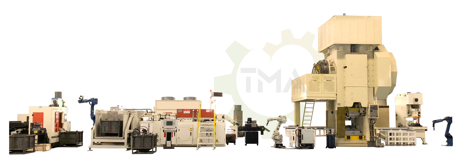
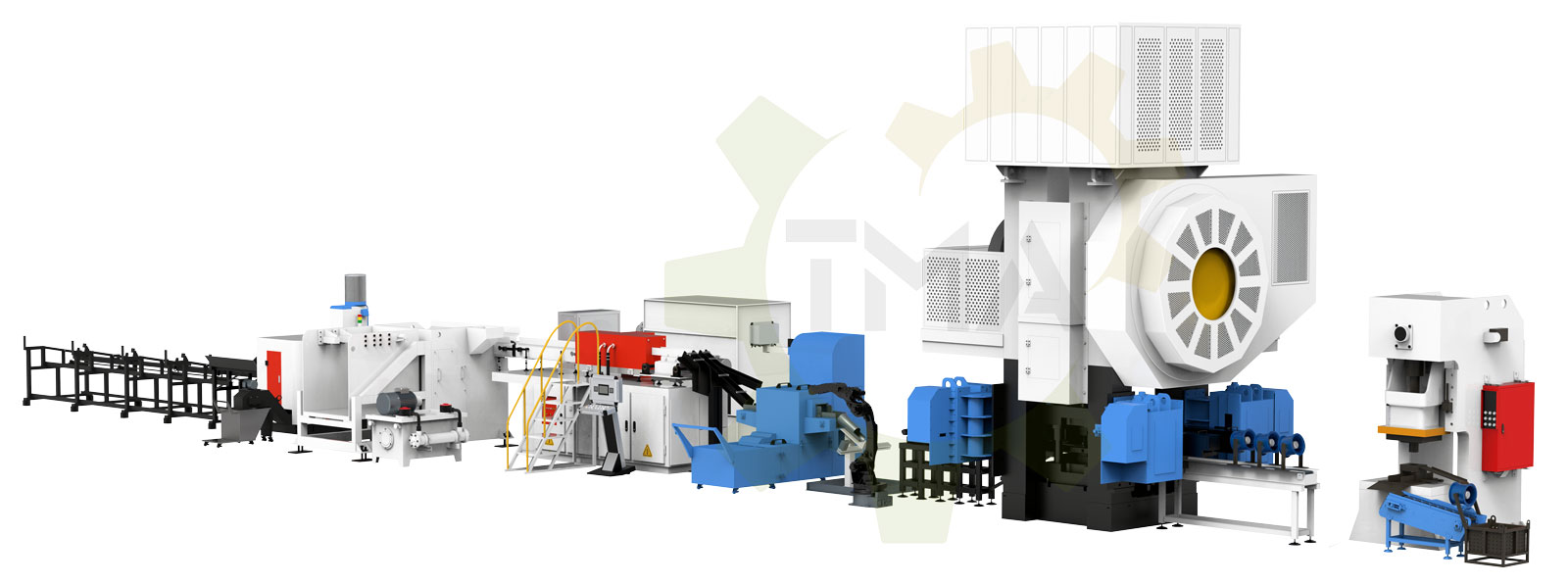
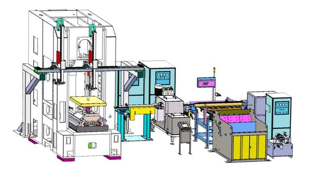
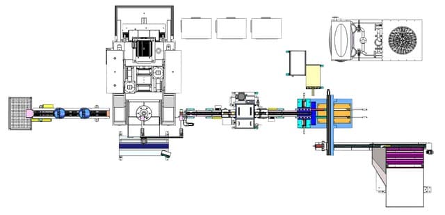
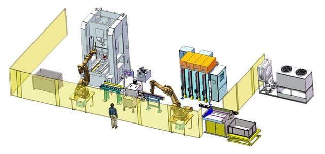
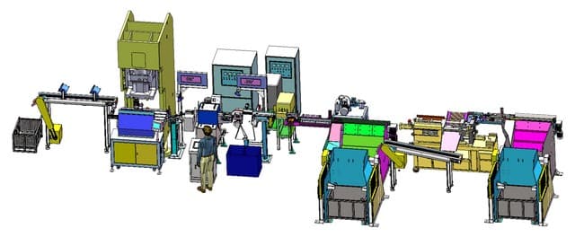
HOT FORGING LINES FOR FASTENERS
Automatic hot forging lines for bolts and nuts
Taiwan Metiz Alliance has been deeply engaged in the industry for many years of forging automation products, and provides forging enterprises with four services: the whole equipment for hot forging production process, automatization of such production lines, green environmental protection technologies and enterprise management consulting.
We are an intelligent manufacturing enterprise of hot forging equipment integrating research and development, design, manufacturing, sales and service, taking the innovative development road, refinement and specialty.
Enterprise mission
- Service small and medium-sized forging enterprises.
- Help forging industry new leap.
- Promote innovative development of diverse industries all around the world.
Enterprise culture
- Create value for customers.
- Create opportunities for employees.
- Create implementations for new science and technology.
Enterprise vision
- Connect 10000+ forging manufacturers.
- Create a greener, more efficient and more high-tech production line.
- Help 1000+ small sizes companies to become big-size companies.
Automatic nut hot forging line
Full design of the line makes according to the specific customer technical requirements of production process as it shown below or with other customized processes.
Hot forged nut forging process

Video of the Automatic Hot Forging Line for Nut production M18-M30 in operation
Automatic bolt hot forging line
Full design of the line makes according to the specific customer technical requirements of production process as it shown below or with other customized processes.
Long size bolts forging process

Video of the Automatic Hot Forging Line for Bolt production M18-M24 in operation
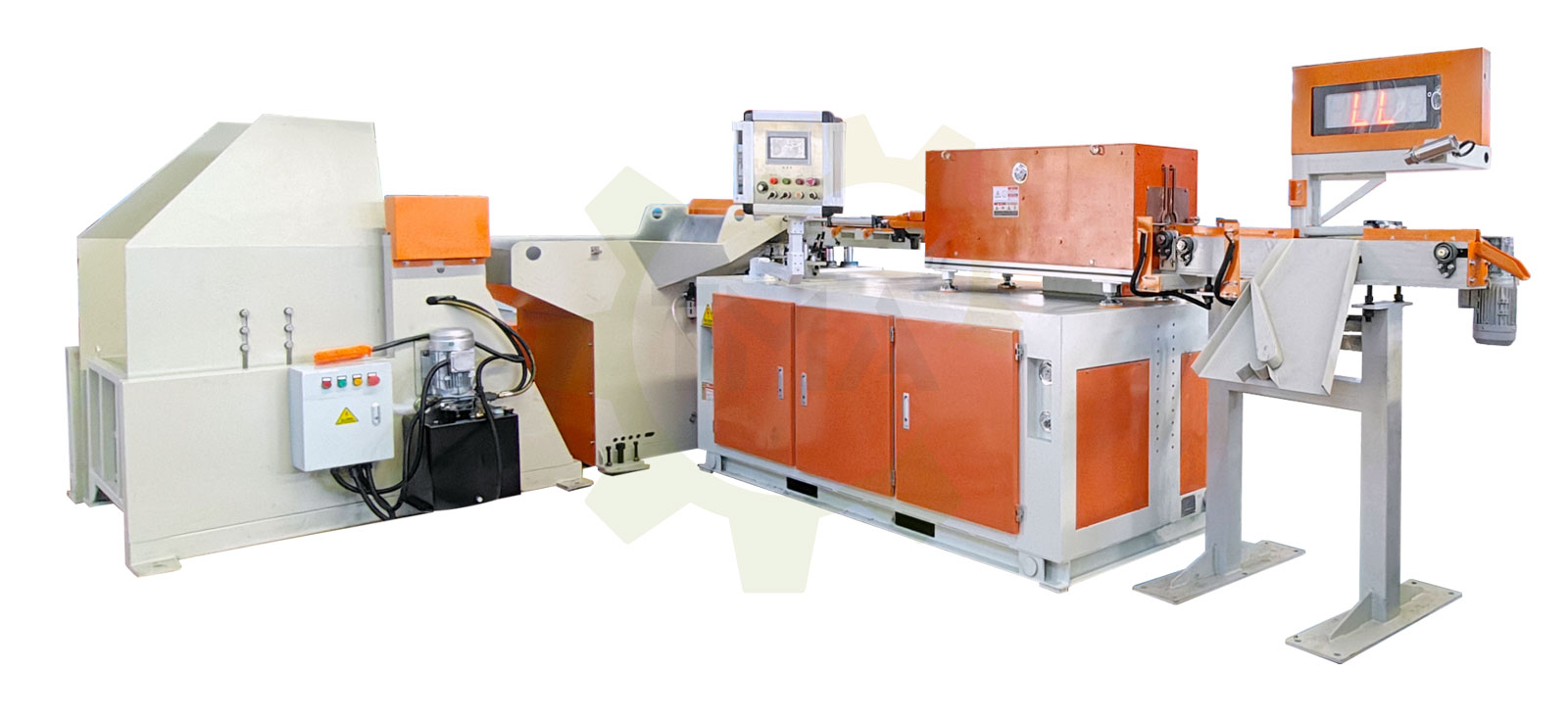
Tipping and feeding equipment
The hydraulic tipping unit transfers raw materials into the feeder, ensuring stable and efficient material loading. This process replaces manual labor, significantly improving production efficiency.
Tipping and feeding equipment features
- The tipping and feeding unit operates using hydraulic power, ensuring stable and reliable loading and unloading.
- Constructed from 10 mm thick high-strength steel, preventing deformation and ensuring a consistent feeding process.
- The lifting module features a linear track with a dust-proof function for extended durability.
| Model No. | Size of units, mm | Power, KW | Loading capacity, kg | Suitable blank diameters, mm | Driving system | Type of conveyor chain |
|---|---|---|---|---|---|---|
| CF-TSJ-15-30 | 1500 × 800 × 1200 | 10 | 0-1000 | Ø15-30 | Inverter motor | Single / Double chain |
| CF-TSJ-30-50 | 1500 × 900 × 1200 | 0-1500 | Ø30-50 | |||
| CF-TSJ-50-70 | 1500 × 1000 × 1200 | 15 | 0-2000 | Ø50-70 | ||
| CF-TSJ-70-90 | 1500 × 1100 × 1200 | 0-2500 | Ø70-90 | |||
| CF-TSJ-F | / | |||||
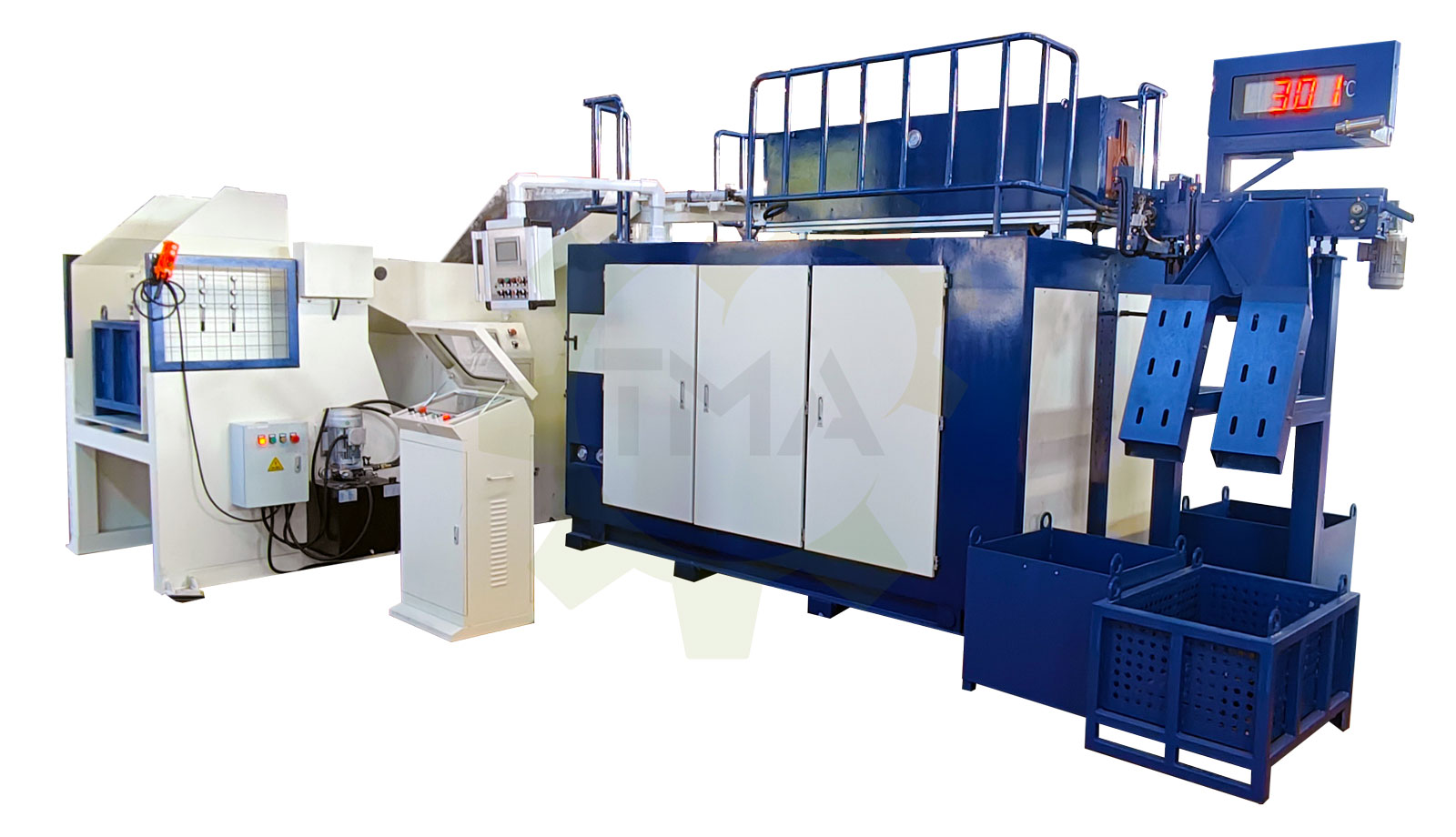
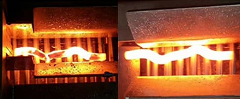
Induction heating furnace
A well-thought-out design reduces the furnace height, making maintenance simpler and more convenient while ensuring high-speed and uniform heating.
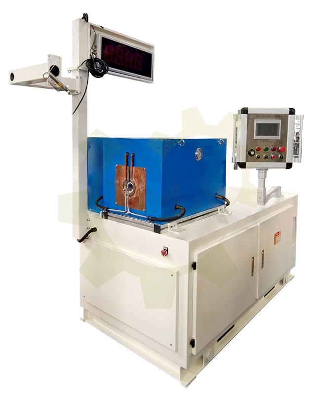
Induction heating furnace features
- Full digital control ensures high accuracy and reliability.Voltage and current dual closed-loop control system for improved stability.
- Advanced protection system with high power factor operation.
- Optimized external control interface, ensuring 100% power-on efficiency.
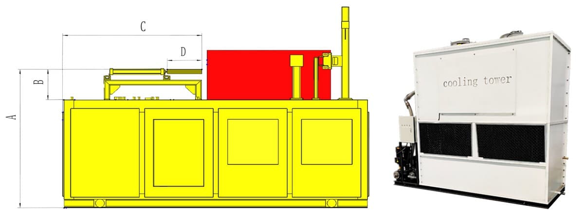
| Parameters of induction heating furnace | Parameter of cooling tower | ||||||
|---|---|---|---|---|---|---|---|
| Model No. | Input voltage, V | Output power, kw | Cooling water consumption, T/H | Cooling hydraulic pressure, MPa | Unit type | Dimensions, mm | Main pump (power, flow, lift) |
| CF-IGBT-100KW | 3-380 | 100 | 3 | 0.2-0.3 | 10T | 2400 × 9100 × 2150 | 3kw, 23m3/h, 28m |
| CF-IGBT-200KW | 200 | 5 | 20T | 3200 × 9100 × 2200 | 3kw, 23m3/h, 28m | ||
| CF-IGBT-300KW | 300 | 8 | 40T | 3200 × 1160 × 2400 | 4kw, 25m3/h, 28m | ||
| CF-IGBT-400KW | 400 | 12 | 50T | 3800 × 1160 × 2450 | 5.5kw, 46m3/h, 28m | ||
| CF-IGBT-500KW | 500 | 15 | 60T | 2900 × 1160 × 2700 1100 × 1000 × 1800 | 7.5kw, 50m3/h, 32m | ||
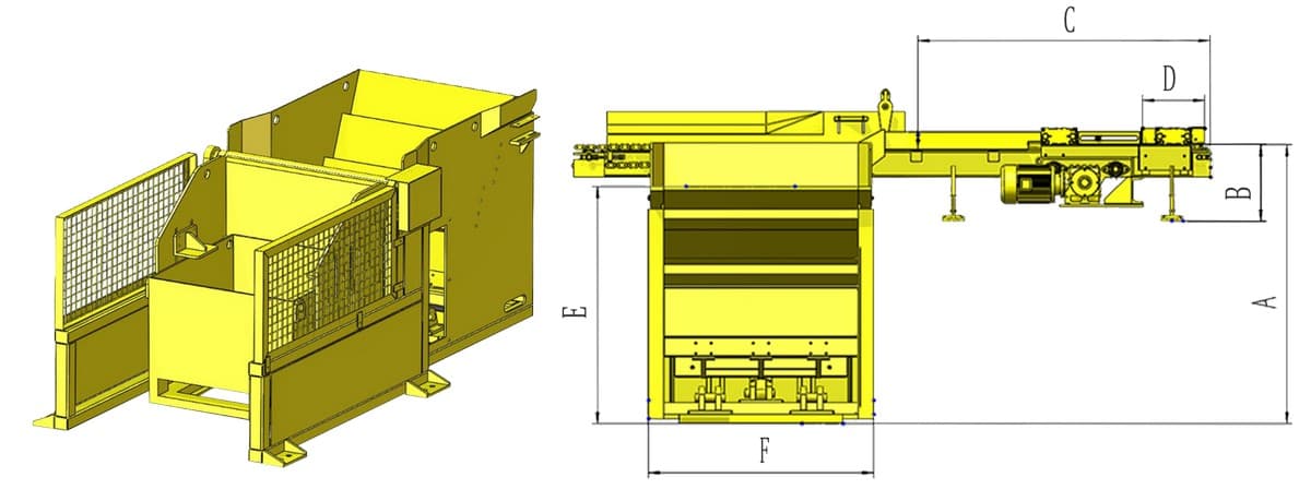
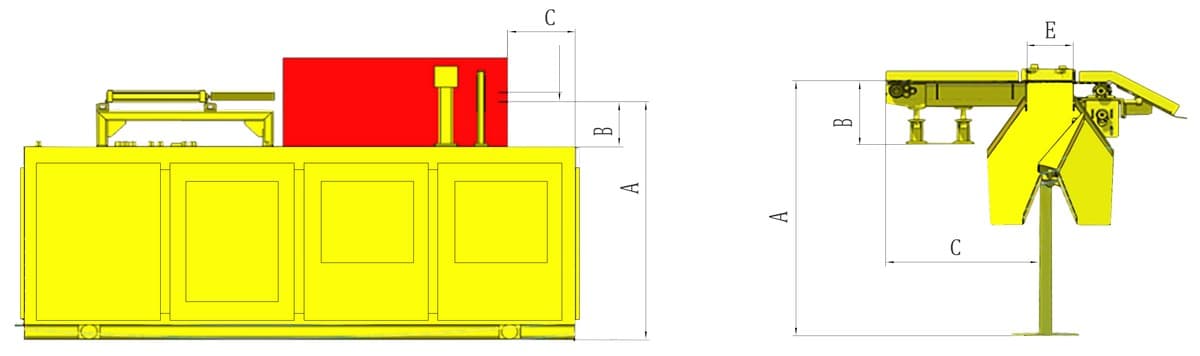
The height B from the intermediate-frequency furnace table to the bottom of the furnace discharge port determines the height B from the bottom of the three-stage selection fixed bracket to the conveyor chain.
The distance C from the furnace mouth to the side of the intermediate-frequency furnace determines the distance C from the three-stage selection entrance to the ground support frame.
The bar diameter D determines the conveyor chain width.
The bar length determines the discharge port size E of the three-stage selection.
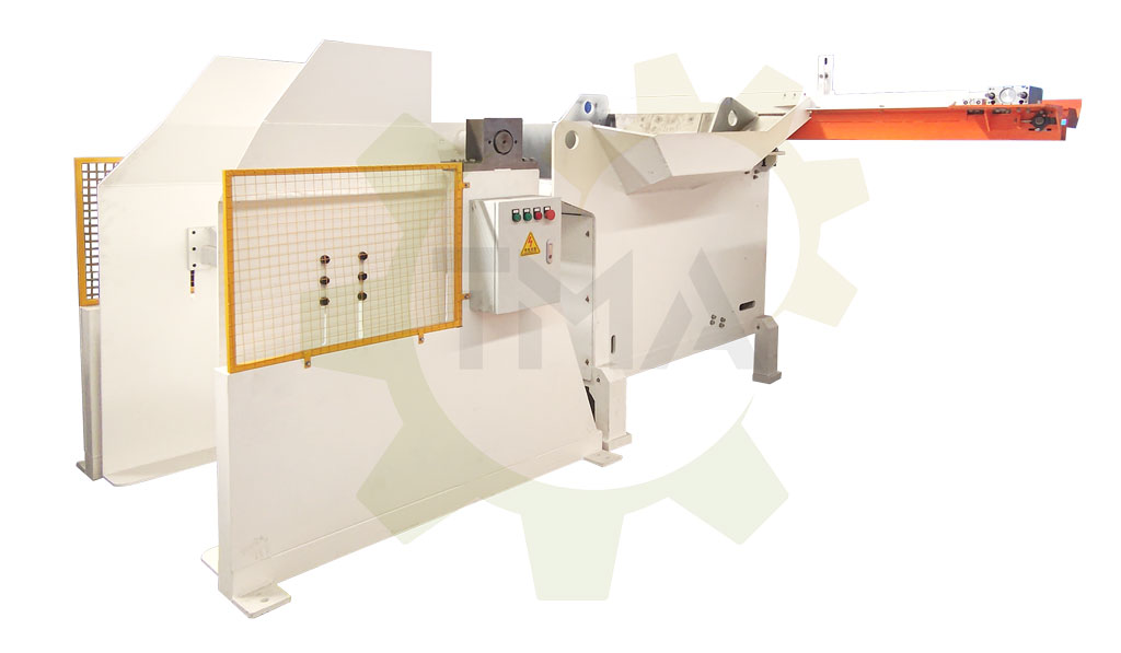
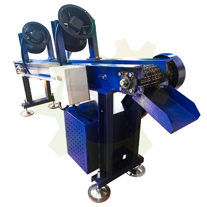
Temperature sorting equipment
This equipment works with the medium-frequency furnace to ensure that the blank temperature meets the required standards. The structure is height-adjustable and can be directly connected to the intermediate-frequency furnace and fixed to the floor. Customers can purchase this equipment separately and integrate it into their existing furnace systems. We also provide one-stop customized services, including design, assembly, installation, and post-maintenance.
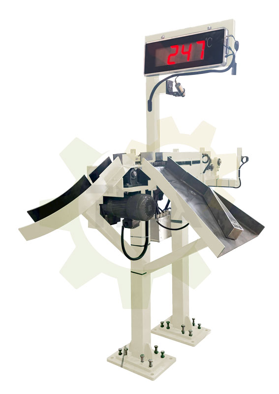
Temperature sorting equipment features
- Automatic temperature monitoring and sorting system with three-stage selection for accurate blank classification.
- Adjustable distance between the conveying connection point and the medium-frequency furnace for smooth material transfer.
- Easy installation and stable operation.
| Model No. | Exporting height | Diameter of blank, mm | Length of blank, mm | Load capacity, kg | Chain specifications | Additional function |
|---|---|---|---|---|---|---|
| CF-FXJ-15-30 | Height of the furnace door ±100mm | 15-30 | 30-100 | Below 5kg | 8A / 10A / 12A | Butt hopper |
| CF-FXJ-30-50 | 30-50 | 50-150 | Below 10kg | 10A / 12A / 16A | ||
| CF-FXJ-50-70 | 50-70 | 80-200 | Below 20kg | 16A / 20A / 24A | ||
| CF-FXJ-70-90 | 70-90 | 100-250 | Below 30kg | 16A / 20A / 24A |
The height B from the intermediatefrequency furnace table to the bottom of the furnace discharge port determines the height B from the bottom of the three-stage selection fixed bracket to the conveyor chain.
The distance C from the furnace mouth to the side of the intermediate-frequency furnace determines the distance C from the three-stage selection entrance to the ground support frame.
The bar diameter D determines the conveyor chain width.
The bar length determines the discharge port size E of the three-stage selection.
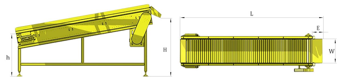
Final Product Conveyor
The conveyor system is designed based on product types and processing methods. It can be customized as a single-row conveyor, double-row conveyor, string conveyor, plate chain conveyor, or mesh chain conveyor, ensuring flexibility for various applications.
Conveyor features
- High temperature resistance with no deformation.
- Lightweight yet strong, with excellent wear and impact resistance.
- Energy-efficient design ensuring stable transmission and low failure rates.
- User-friendly maintenance for an extended service life.
| Name | Model No. | Inlet height | Outlet height | Width | Length | Speed | Material | Driving system | Surface treatment |
|---|---|---|---|---|---|---|---|---|---|
| Conveyor chain | CF-SSL-W-L | h | H | W | L | V | Carbon steel / Stainless steel | Frequency conversion / Speed regulation | Paint / Spray |
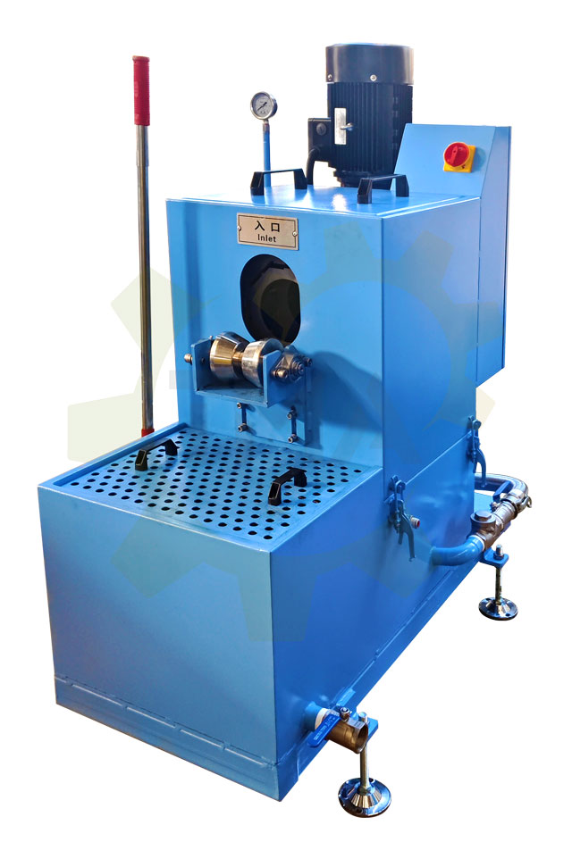
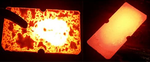
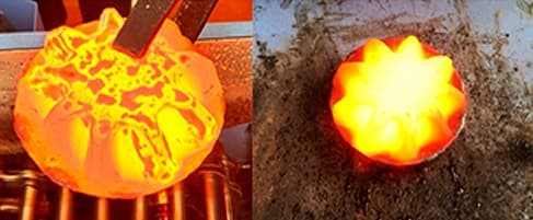
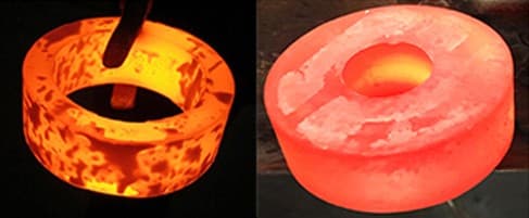
Descaling machine
Also known as an oxide cleaning machine, it features a stainless steel chain design with a multi-layer filtration system to achieve 360° all-around oxide cleaning with effective collection.
The machine removes over 95% of oxides formed after induction heating, making it an essential component in hot forging lines. As hot forging manufacturers upgrade their existing production lines, our descaling machine can be seamlessly integrated into their current systems.
Descaling machine features
- Effectively removes oxidation from workpieces after induction heating.
- Improves surface quality of final products.
- Extends mold lifespan and increases product pass rate
- Reduces raw material consumption and overall production costs.
| Model | Size of unit (length × width × height), mm | Power, kw | Working pressure, MPa | Water tank material | Suitable for bar diameters, mm | After forging size (width × height), mm | Nozzle quantity, pcs | Chain specification | Driving system |
|---|---|---|---|---|---|---|---|---|---|
| CF-BP-50 | 1200×1150×1200 | 4.37 | 1.2-1.6 | 304 | Ø15-50 | 100×50 | 12 | 12A | Variable frequency motor |
| CF-BP-80-100 | 1420×1530×1470 | 8.25 | 1.6-2.0 | Ø20-80 | 100×80 | 16 | |||
| CF-BP-80-160 | 1420×1530×1470 | 8.25 | 1.6-2.0 | Ø20-80 | 160×80 | 16 | |||
| CF-BP-120-160 | 1620×1550×1600 | 11.75 | 1.6-2.0 | Ø55-120 | 160×120 | 24 | |||
| CF-BP-120-220 | 1620×1550×1600 | 11.75 | 1.6-2.0 | Ø55-120 | 220×120 | 24 | |||
| CF-BP-100-S | 1620×1610×1500 | 15.75 | 2.8-3.5 | Ø60-100 | 100×100 | 16 | |||
| CF-BP-100-S | 1620×1610×1610 | 22.75 | 2.8-3.5 | Ø80-150 | 160×150 | 24 | |||
| CF-SF-50 | 1200×1150×1000 | 4.37 | 1.2-1.6 | Ø15-50 | 100×50 | 12 | Servo motor | ||
| CF-SF-80-100 | 1420×1530×1270 | 8.25 | 1.6-2.0 | Ø20-80 | 100×80 | 16 | |||
| CF-SF-80-160 | 1420×1530×1270 | 8.25 | 1.6-2.0 | Ø20-80 | 160×80 | 16 | |||
| CF-SF-120-160 | 1620×1550×1400 | 15.75 | 1.6-2.0 | Ø55-120 | 160×120 | 24 | |||
| CF-SF-120-220 | 1620×1550×1400 | 15.75 | 1.6-2.0 | Ø55-120 | 220×120 | 24 |
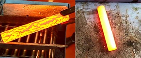
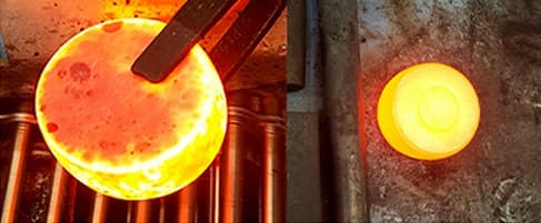
BEFORE AND AFTER DESCALING
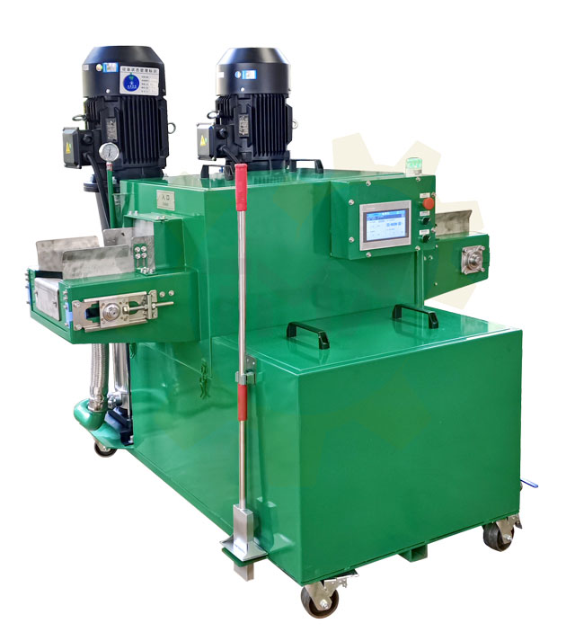
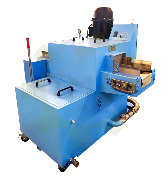
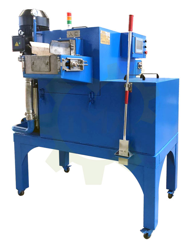
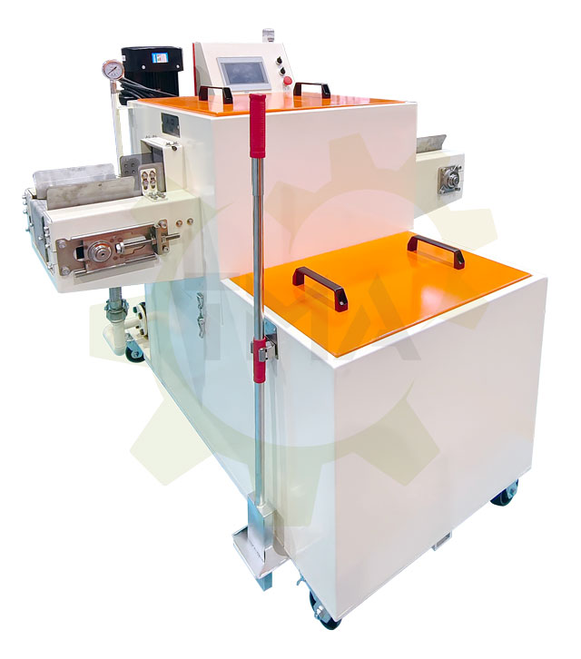
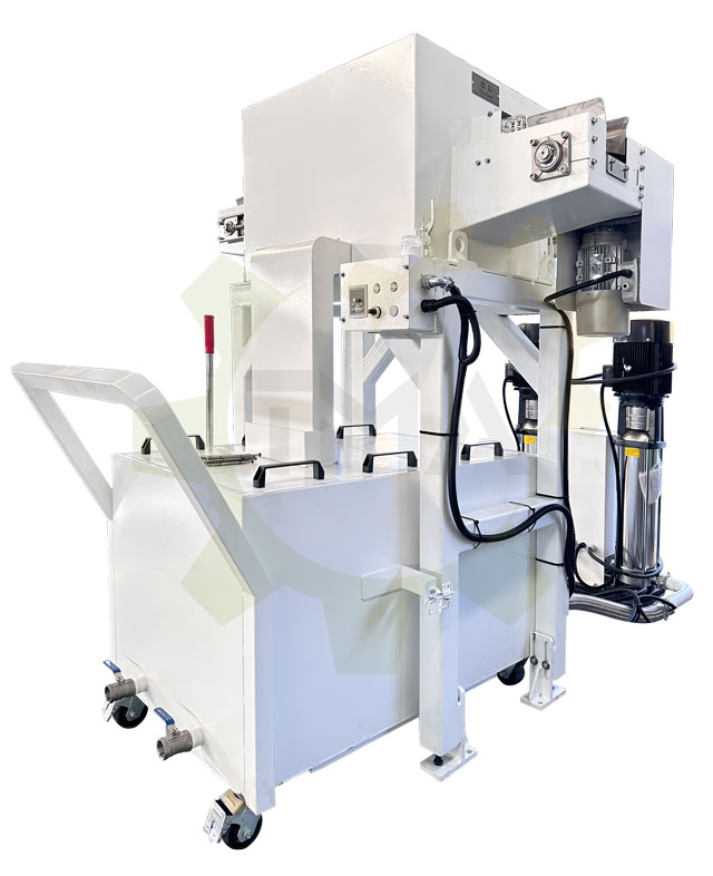
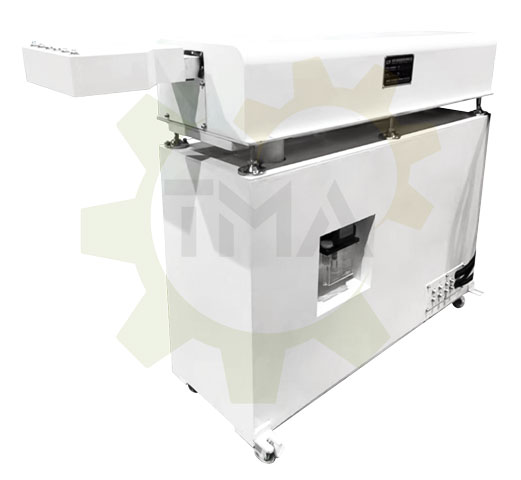
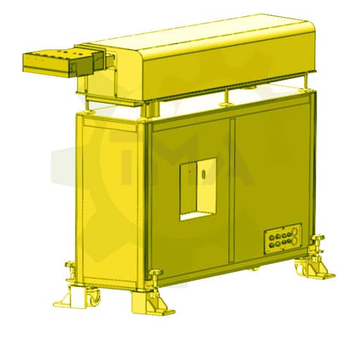
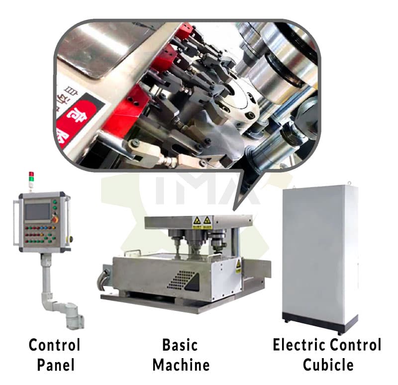
LUBRICATION WORKSTATION
The lubrication workstation stores and supplies release agents to automatic lubrication equipment. The graphite box is made from stainless steel sheet metal. It features a separate lubrication and cleaning system to enable automatic lubrication and cleaning. This ensures seamless integration with automated forging production.
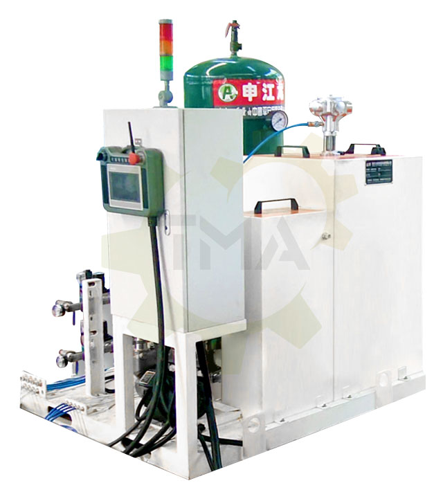
Lubrication workstation features
- Centralized release agent storage and distribution.
- Pressurized tank system ensures fine mist atomization of the release agent.
- High-output jet system effectively removes residual oxides from mold surfaces.
| Name | Model | Storage tank | Workstation installation space | Air connection | Air (proof) curtain | Air compressor exhaust volume | Reserved load switch | Power selection | Rhythm | Covering area, mm | Installation way | Spray pattern |
|---|---|---|---|---|---|---|---|---|---|---|---|---|
| Single station | CF-RHJ-S-1 | 1 | 1250 × 1250 × 1550 | DN25 DN32 | Optional 1-way/2-way. 1 or 2 routs are available | Above 1.5 m3/min | ≥D25 | Slider / Lead screw | 2 - 4 seconds | Ø50 - 150 (custom) | Side installation: floor-standing room moves backward. Rear installation: floor-standing type moves sideways or backwards. Rear installation: open door type flips sideways. | Fan / atomized/ cylindrical |
| Double station | CF-RHJ-S-2 | 1 or 2 | 1250 × 1250 × 1550 | Above 3 m3/min | ≥D32 |
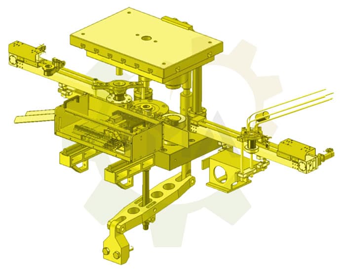
Automatic lubrication equipment
This compact and space-saving lubrication equipment features a sleek design and servo-controlled stroke, making it ideal for forging demolding. Before forging, the system performs three spraying operations: first spray – compressed air, second spray – demolding agent, third spray – compressed air again. This reduces mold adhesion and enhances the demolding process for better product quality.
Automatic lubrication equipment features
- Precision nozzle atomization with simulated product profiling design for even spraying.
- Adjustable localized spraying for improved demolding.
- High efficiency—completes a full lubrication cycle in just 2 seconds.
- Automatic cleaning of nozzles and pipelines for extended service life.
- Space-saving design with easy maintenance and quick mold replacement.
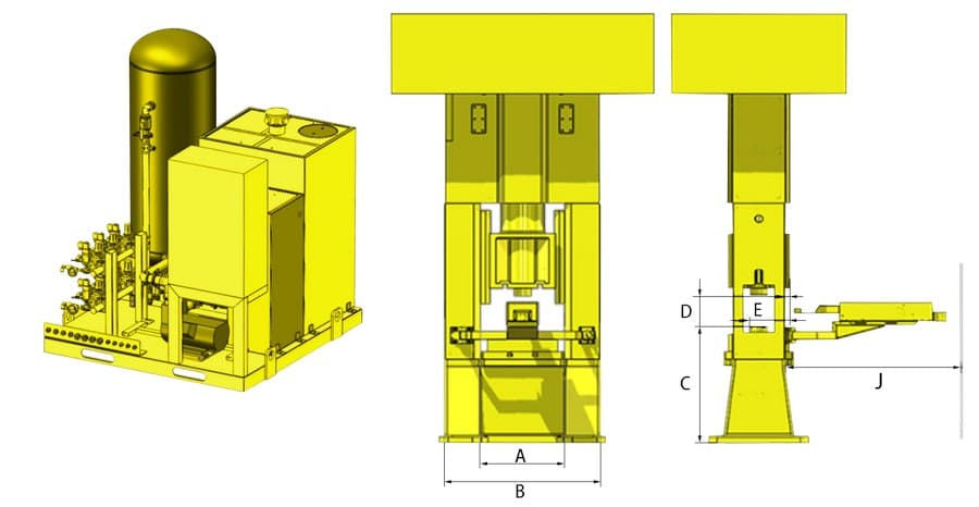
Open-door type lubrication equipment
Open-door type: A and B dimensions determine the fixed width of the equipment, C dimension is the height from the lower mold to the ground, D dimension is the striking distance between the upper and lower molds, and E is the farthest distance from the fixed surface to the cavity.
F is the distance from the hammer head to the fixed surface (the hammer head can be inside or outside the fixed surface), and J dimension is the size of the space behind the main machine.
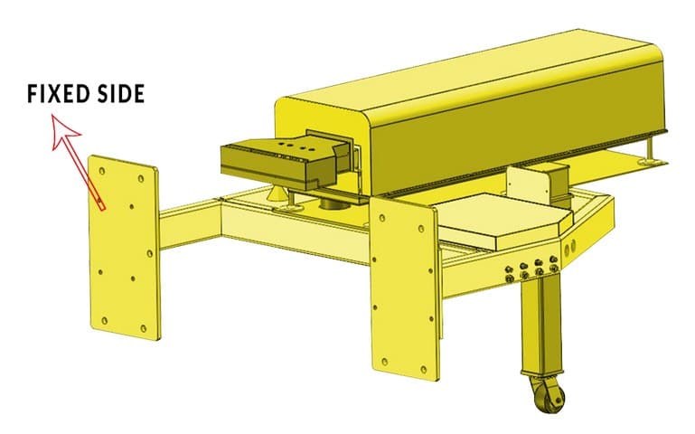
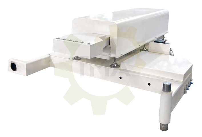
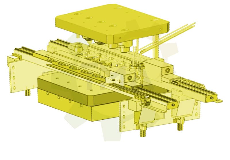
Floor-standing type lubrication equipment
Floor-standing type: C is the height from the lower mold to the ground, D is the striking distance between the upper and lower molds, F is the distance from the hammer head to the fixed surface, and E is the farthest distance from the fixed surface to the cavity.
F is the distance from the hammer head to the fixed surface (the hammer head can be inside or outside the fixed surface), and J is the space behind or on the side of the main machine.
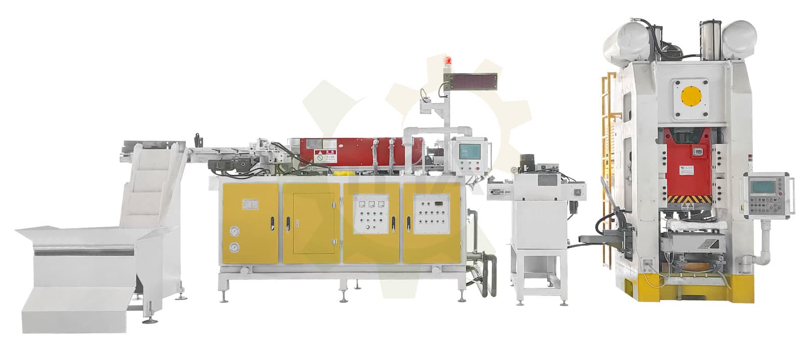
Automatic walking beam
Also known as a walking beam conveyor, this system ensures synchronous bar movement across multiple stations. It operates in sync with a press or punch press, automating the forging process. The robotic system replaces manual labor, significantly improving efficiency and product uniformity.
Automatic walking beam features
- Centralized master control system with one-button start/stop.
- X-axis: Driven by active motor, ensuring high precision and low failure rate.
- Y-axis: Four synchronized servo motors, guaranteeing accuracy within 100 microns and featuring automatic floating functionality.
- Z-axis: Equipped with a braking system and balance mechanism, reducing damage from accidental collisions.
| Name | Stroke, mm | Power, kw | Control method | Degree of freedom | Drive system | Installation method | Synchronization method | Float or not | Use the product | Use the tool |
|---|---|---|---|---|---|---|---|---|---|---|
| X-axis | 300 - 400 | 10-15 | One - side 2-bit control | 1 | Electronic control | Fixed on the Y-axis | Active + follow-up | No | / | / |
| Y-axis | 200 - 400 | 10-20 | Two - side 4-bit control | Fixed on the Z-axis | 4-bit synchronization | Yes | ||||
| Z-axis | 200 - 300 | 15-20 | Machine side mounting | |||||||
| Overall | / | 35-45 | 10-bit synchronization 2-bit follow up | 3 | Electronic + air control | Simultaneous installation in Y and Z axis and machine side mounting | 3 groups of 4-bit synchronization | Circle form products with weight more than 1kg | Hot die forging press |
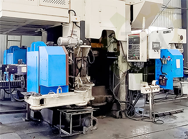
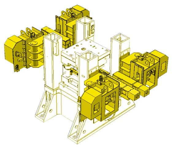
Single / Double side manipulator
The single/double-sided manipulator is a multi-station hot forging manipulator that integrates multiple mold sets into a single punch press, enabling continuous automated production. This system improves automation in material handling, workpiece loading/unloading, and tool replacement. The use of 3D stamping manipulators further enhances efficiency in production.
Equipment features
- Quick and easy V-clamp replacement by loosening a single bolt.
- Adjustable clamp installation to minimize concentricity deviation errors.
- Advanced punch monitoring system detects broken punches, preventing mold damage and ensuring continuous production.
| Model | Loading, kg | Production beat, pcs/min | Driving system | Environment temperature | Installation Method |
|---|---|---|---|---|---|
| CF-D-5 | 5 | 25±5 | AC servo | 0 - 50°C | Fuselage mounting |
| CF-S-10 | 10 |
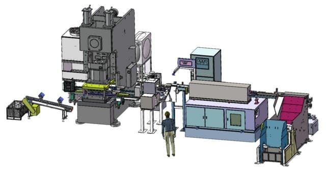
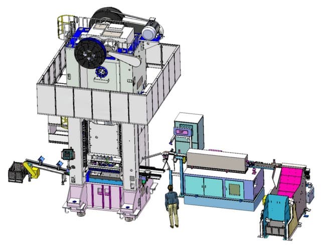
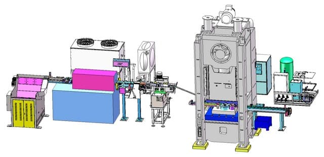
Completed Projects of Hot Forging Lines