STEEL WIRE DRAWING MACHINES
HORIZONTAL TYPE WIRE DRAWING LINE
The horizontal type wire drawing line includes RGT-3100A vertical wire unwinder, RG-SB7 combined descaler with descaling rollers and steel brushes, RGTD straight line wire drawing machine (number of capstans according to the Customer’s request) and horizontal spooler RGT-2000.
Optional devices for sharpening and welding of wire are available. The drawing line is optionally equipped with Industry 4.0 compliant software (intelligent line control, remote diagnostics and troubleshooting).
The drawing machine, at the request of the Customer, can be equipped with both traditional monolithic dies and cassette roller dies (cold rolling cassettes).
Monthly output of a horizontal type wire drawing line equipped with roller cassettes, provided that it works in 2 shifts × 20 hours × 30 days, will be 435 tons/month. This productivity is achieved when drawing Ø1.6 mm mild steel wire with a production efficiency of 85%.
Horizontal Type Wire Drawing Machine
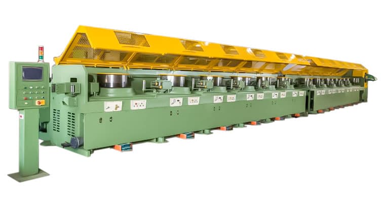
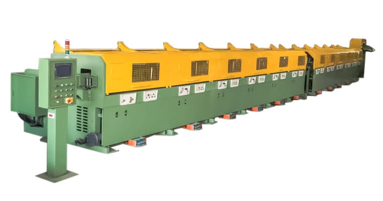
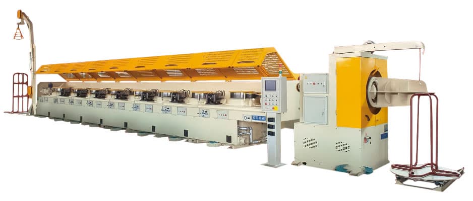
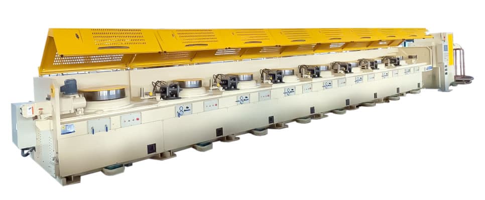
Specification of drawing machine RGTD-670×1B + 550×8B with spooler RGT-2000
| Model | Inlet Diameter | Outlet Diameter | Total A.R.R | AVG A.R.R | Capstans | Capstan Motor | Drawing Speed Max. | Capacity, MTS/HR | Number of Drawing Dies | Winding Weight, MTS/PC | Total Power Consumption |
|---|---|---|---|---|---|---|---|---|---|---|---|
| RGTD-670×1B + 550×8B | Ø6.5 mm | Ø1.6 mm | 93.9% | 26.71% | Ø550 mm×1 pcs, Ø670 mm×8 pcs | 60 HP×9 pcs | 900 m/min | 0.85 | 9 | - | 628 HP |
| RGT-2000 | Ø1.6 mm | - | - | - | - | - | 0.5 - 1.5 | ||||
Horizontal Wire Drawing Machine Features
- Wire Drawing Range: Ø6.5 mm (inlet) ~ Ø1.6 mm (outlet)
- All 9 capstans in the Wire Drawing Machine are driven by 60HP AC Inverter SIEMENS Motor (3 phase) with MITSUBISHI Inverter Drives.
- Final Max. Speed: 900 m/min. (w/ Roller Cassette).
- Power Source: 380V / 50Hz / 3 Phase.
- Control Method :
- Synchronization from Capstan Blocks 1st ~ Last are controlled by Dancer System.
- Adopts Linking, Jogging, and Foot Pedal Control Mode.
- By-pass capability for all individual blocks and function of acting as outlet block.
- Speed adjusted via PLC automatic control programme.
- Hydraulic Disc Brakes mounted on each capstan block.
- Automatic detection for electrical and mechanial issues, such as snarls and wire breakage, preventing machine damage.
- The HMI control interface can display all fail-safe alarms and detections.
- HMI Main Control Console:
- HMI control console includes a touch display monitor with keyboard interface for setting input and output parameters of each individual block.
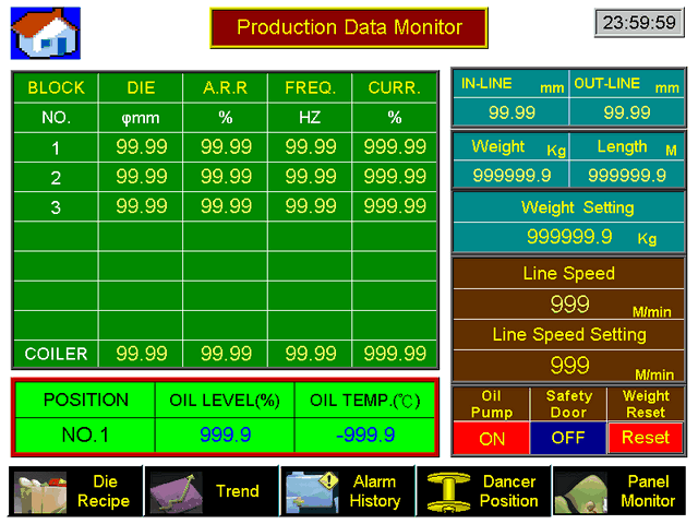
- The HMI console will display all various statuses and parameters, not limited to but including Line Speed, Frequency & Current, the Reduction per Draft, Individual Capstan Speed, and all possible warnings & errors.
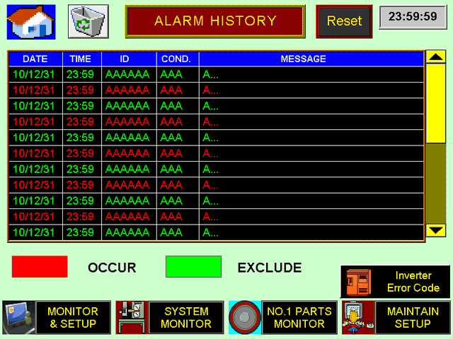
- Memory of errors and alarms are recorded on the system's history log for analysis and troubleshooting.
- Optional Hardware – the PLC system can be linked to a network through a PLC network transmodule to allow for remote assistance and troubleshooting including data collection on a local network by a MIS system and data server.
- Drawing line capstans (blocks):
- 1st Block - Ø670 mm Drum (OTO Type - Overhead Take-Off Type)×1 pcs used as Wire Storage Type Block.
All capstan blocks after the OTO will adjust and slow down in speed to allow troublshooting of trouble wire such as snarls during wire feeding.
OTO 1st Block can be stopped while the 2nd Block and after are capable of non-stop running. This provides negligible downtime during troubleshooting equating to higher production efficiency.
Guide roller adopts sensor to detect and adjust the speed, ensuring smooth storage of wire by automatically descreasing and increasing speed when deemed necessary.
All capstans have independent speed control. - 2nd to Last Block consist of Ø550 mm Drum×8 pcs.
- Last Block consists of a double layered drum with exiting X & Y straightening rollers for tension control.
- Material : Cast Iron (FCD-45) with a Hardness of 40 HRC±2.
- The drum surface is mirror-polished to futher harden the surface and prevent wire abrasion.
- Precision tungsten carbide coating on all block surface from the entry root and upwards to a minimum of 150 mm.
- After precision tungsten carbide treatment; the surface hardness will reach 68 HRC±2.
- Block set-up: vertical axis type for first & last block, while the remaining will be tiltled type.
- Block lifetime is approx. 5 ~ 8 years (dependant on maintenance).
- 1st Block - Ø670 mm Drum (OTO Type - Overhead Take-Off Type)×1 pcs used as Wire Storage Type Block.
- Cooling System:
- Water Cooling Capstan with uniquely designed spiral system.
- All internal capstan made of corrosion resistant material.
- Water flow is adjustable at the machine front of every capstan block.
- Die Holders:
- Rotary Die Holder: 1st Block.
- Roller Cassette: 2nd Block ~ Last Block.
- Dry lubricant soap for 1st-Block Rotary Die Holder only; Roller Cassette does not require lubricant for cold rolling.
- Patented design adopting double pressure dies providing uniformed lubrication and prolonged die life.
- Elongated Diebox / Holder to provide better lubrication and roundness during drawing.
- Side loading cartridge type suitable for single die or double pressure die.
- Cartridges implemented with quick tool-free removal allowing for a quick change of Die.
- Die Type: JIS Standard Type (to be advised by Buyer if different standards are used).
- Die Holder Adjustment: Up / Down, Left / Right.
- Water cooling implemented for Die Holder (Diebox).
- Anti-Vibration Rollers are implemented on each individual capstan block.
- Pressure Switches are installed on the machine to prevent wire break during pressure cut-off.
- Pressing Wire Roller by Pneumatic Cylinder: to prevent wire slippage on drum, during machine stoppage, the pressing roller located on the hindside of each individual capstan block will steadily push and hold the wire in place to prevent any slippage during restart.
- Wire entry direction: (to be advised by Buyer).
- Stop & Halt Times:
- Normal Stop Time: programmable by user.
- Quick Stop: 5 sec. without wire break.
- Emergency Stop: 0.5 sec. ~ 3 sec. w/ additional wire breaking.
- The drawing machine is equipped with a digital wire length counter.
- Capstan Block Control Panel:
- A control panel is foreseen for each individual capstan block and includes all the basic push-buttons and selectors for operating the drawing machine, including an emergency stop button on every individual control panel.
- Water valves for all Die Holder and Capstan Blocks.
- Manometer for the Dancer System's Pneumatic Cylinder.
- Equipment for Industrial Safety:
- Equipment safety guard and lock to protect the operator from accidental wire swing and breakage during operations.
- Safety guard fail safe protection is adjustable via HMI for automatic stoppage during opening or to slow production speed down to a minimum value for inspection purposes.
- Hydraulic pinch roller prevents swaying of the wire end and prevents injury from wire ending or breakage.
- Frame is equipped with protection warning lights that are synchronized to a timer and the PLC's control system. Safety warning lights adopt international standard green / yellow / red colour lighting.
- СC.E. & ISO-9001 Safety & Quality certified.
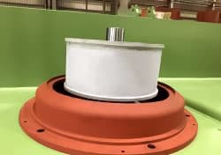
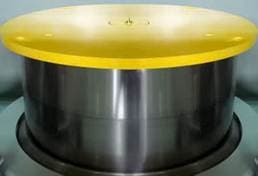
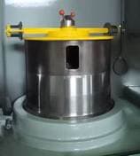
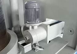
Cassette Roller Die (Cold Rolling Cassette)
Roller Cassettes for drawing lines are used along with monolithic dies traditional for multi-pass drawing lines. The new drawing technology using cold roller cassettes achieves better energy savings and lower carbon emissions. The main advantage of a cassette roller die is a low coefficient of contact friction. In roller dies, the contact friction corresponds to rolling friction, which is 5 times less than the sliding friction of traditional monolithic dies.
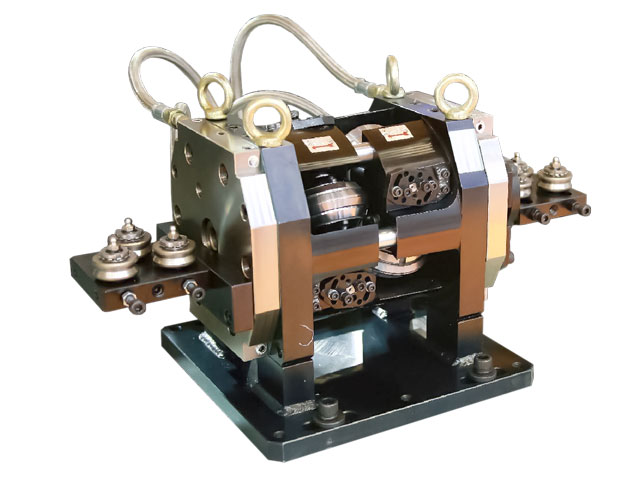
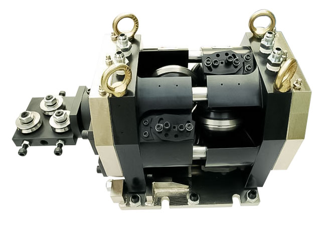
The use of cassette roller die in wire production technology can significantly reduce the cost of its production due to the wider use of mechanical preparation of the metal surface for drawing and the overall increase in drawing speeds. Another important factor for the use of this technology for the production of wire is the improvement of the environment by reducing the proportion of pickled metal and the rejection of the use of technological lubricants, without which it is impossible to imagine drawing using traditional dies.
Modern roller cassettes are applicable for high speed drawing of high/ medium/ low carbon round/ hex/ ribbed wire rod, alloy/ stainless steel wire, copper/ titanium/ other metal wire. The working diameter of wire rod for such drawing dies is from 20 mm to 1 mm. Roundness tolerance approx. Ø0.02 mm (depending on wire size).
Advatanges of cold rolling with Cold Rolling Cassette
- Roller Cassette System ideal for small diamater high speed production enabling a roundness tolerance of 0.02 mm and lower.
- Speed and productivity gains thanks to roller rolling technology.
- Long production runs of approx. 3000 tons, before regrinding of roller rings are required, with minimal stoppage downtime for a high production efficiency.
- Reduction in lubricant.
- Reduction in power consumption (approx. 10% less power) with a higher production speed than conventional die drawing.
- The consumption of drawing powder has been reduced several times.
- Low energy consumption due to the low coefficient of friction of the rollers.
- Cassette Roller Die System produces a bright clean outlet wire with negligible lubricant residual that is ideal of post-process treatment such as pickling and annealing - shortening the original pickling time with less by-product waste sludge produced, and depending on the final product, a pickle-less annealing process is achievable.
- Presents a healthier working environment for operators that would otherwise be more hazardous in a conventional die drawing environment.

Cold Rolling Cassette Features
- Inlet → Outlet: Ø5.5 mm ~ Ø1.6 mm.
- Six Pins (Ø25 mm) with oil cooling design that are designated to supply and circulate oil to the roller-holder bearings.
- Six Pure Tungsten Carbide Roller Rings w/ Dimensions: Ø90 mm × Ø65 mm × 15 mm.
- Six Roller Holders (Pin Ø25 mm) with replaceable bearings. These bearings will be substituted and replaced if the complete Roller Holder + Roller Ring are returned to our service center for maintenance and regrinding.
- Adopts individual axial and radial roll adjustment.
- Internal circulation and lubrication network for the Roller Holder Bearings.
- Entry Wire Guiding Panel (where deemed necessary).
- Standard Base Plate.
Roller Cassette protection measures (implemented only on our equipment)
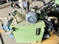
- Roller Cassette adopts oil cooling circulation and oil recovery system via the oil circulation pumping unit implemented with four water cooling tube-tank.
- When the oil circulation pumping unit's flow vlave detects oil loss, the machine will automatically stop and display a HMI notification alarm. Each outlet has a screening and magnetic filter to help maintain oil cleanliness.
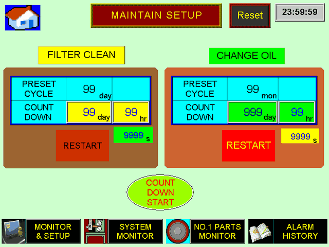
- When the motor pump of the oil circulation unit fails, the machine will automatically stop and display a HMI notification alarm, including notification for oil replacement and maintenance.
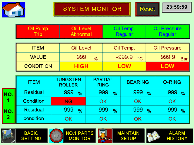
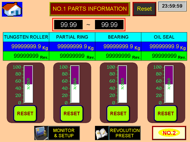
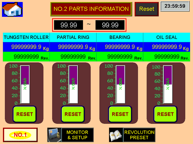
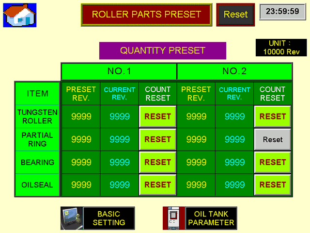
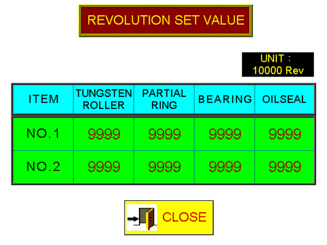
- The maintenance reminder software for the consumables parts such as Bearings, Oil seal / O-Ring, and Tungsten Roller Ring will be displayed on the HMI monitor. An alarm will be triggered when the service life reaches 90% and will automatically stop when it reaches 95%. This failsafe system is to prevent damage to the Roller Cassette Unit and to help prolong its service life.
- Memory counter for all consumables, resettable from zero, will be displayed on the HMI interface.
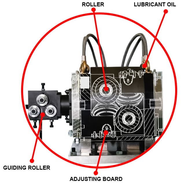
Comparison of drawing machine RGTD-750×1B + 670×7B performance with roller cassettes and solid dies
| Drawing with drawing dies | Drawing with roller cassettes | Features and benefits of drawing with roller cassettes | |
|---|---|---|---|
| Inlet Diameter | 8.00 mm | ||
| Outlet Diameter | 3.00 mm | ||
| Total A.R.R | 85.9% | ||
| AVG A.R.R | 21.72% | ||
| Drawing Speed Max. | 4 m/sec. 250 m/min. | 5.83 m/sec. 350 m/min. | 30% speed boost |
| Hourly output | 0.83 MTS/HR | 1.17 MTS/HR | |
| Monthly productivity (25 days × 24 hours) | 299 MTS | 562 MTS | Productivity increase by 263 MTS |
| Productivity factor | 60% | 80% | 20% increase in productivity factor |
| Number of Drawing Dies | 8 Dies | 1 Rotary Die + 7 Roller Cassettes | |
| Total power consumption | 704.5 HP | ||
| Winding Weight | 0.8 - 1 MTS/PC | ||
| Tool life | 1 set for 10-15 tons of finished products | 1 set for 3000 tons × 3 = 9000 tons finished products | Increasing the service life of the tool (rollers can be re-sanded 3 times) |
| Operation and cost of drawing powder for 9000 tons | Drawing powder cost NT$115,200 | Drawing powder costа NT$4,800 | Savings NT$110,400 (* see. Note) |
| The need to stop equipment for 3000 tons of products | 8 Dies × 200 times = 1600 times | 1 Rotary Die × 200 times = 200 times | 8 times fewer equipment stops |
| Operating safety | Possible lung infection from inhalation of dust and drawing powder particles | No dust or drawing powder particles | Reducing the cost of protecting workers and the environment. |
| Environmental pollution | The need for waste neutralization | There is no need for waste neutralization | Savings on the wastewater treatment process |
| Degreasing process | Required | Absent | Savings on the degreasing process. |
| Staff training | Time-consuming and costly learning process | Easy and fast learning process | Cost reduction during installation and commissioning, training. |
When using cold rolling cassettes, grease is applied only to the first block.
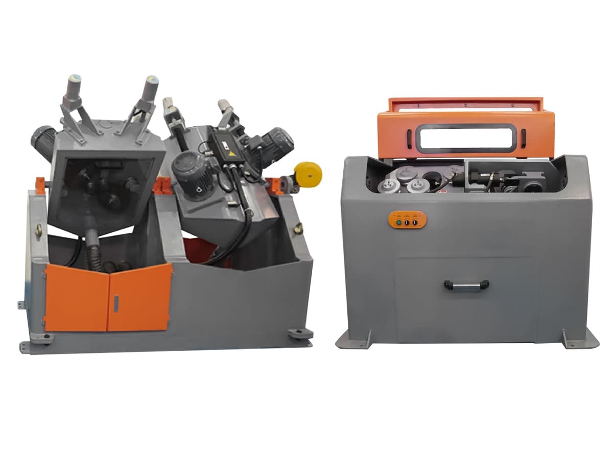
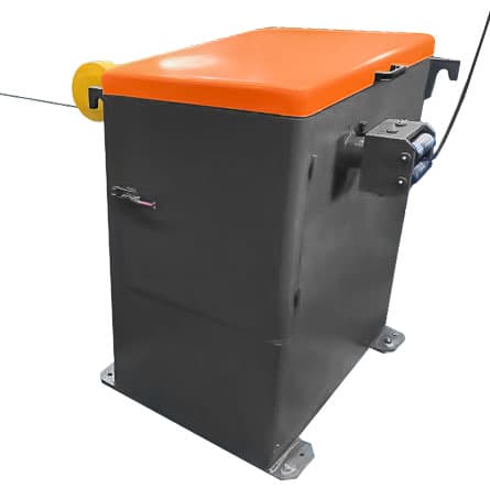
Mechanical Type Bending & Brushing Descaler RG-SB7
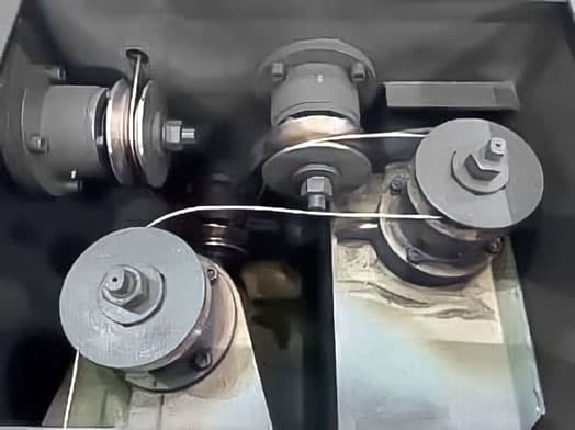
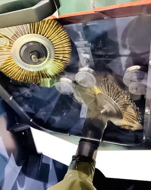
Wire Descaling Machine cleans wire rod from scale mechanically. With this cleaning of the surface from scale, the wire or rod is subjected to periodic kinks in different planes between the rollers, after which the wire goes to the final cleaning with steel brushes. This method of descaling is economically feasible, suitable for surface cleaning, mainly from carbon steel, the dross of which, when bent, is relatively easily destroyed and falls off.
Equipment Features
- Descaling by mechanical bending.
- Mechanical cleaning with brushes.
- Automated control of the steel brushes via PLC control programme to delicately peel off the mill scale layer without damaging the wire rod surface. Function of automatic notification of the replacement of steel brushes.
- This equipment can clean up the mill scale layer of the wire rod and maintain wire cleanliness up to 90%. (A clean wire can greatly help prolong the life of consumable parts such as the drawing die mold and others).
- This equipment can assist and eliminate the need for pre-pickling to save on acid and waste treatment costs.
- Working wire diameter: Ø5.5 mm ~ Ø 7.0 mm (medium carbon steel and low carbon steel). At the request of the Customer, Wire Descaling Machine for cleaning wire with other diameters are supplied.
Mechanical cleaning unit with brushes
- Adopts guiding and straightening rollers to provide uniform brushing.
- Drive Power: 12 HP.
- Alloy Steel Brush: 4× Set of Alloy Steel Brushes and Motors.
- Brushing Motor: 3 HP×4.
- Automatic Brushing Adjustment:
- Brushing Motor w/ electromagnetic switch sensor for automatic adjustment via PLC control system.
- HMI Control & Monitoring Station.
- The speed of the brush cleaning unit is synchronized with the speed of the drawing line.
- Direction: to be advised by Customer.
- Alloy steel brushes with a lifetime usage of approx. 3000 tons.
- Power Source: 380V / 50Hz / 3 Phase.
Bending Descaler
- Bending descaling rollers are made of pure tungsten carbide with an average life of approximately 5 years.
- Descaling rollers are aligned horizontally and vertically at distinctive angles and positions to provide the best possible descaling effect.
- Interior of descaling machine is equipped with a mill-scale collection chute to allow funneling of the mill scales into a waste disposal bag.
Vertical Type Pay-Off RGT-3100A
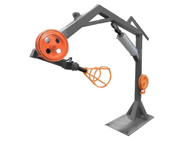
Equipment Features
- Overhead Sheave mounted on the top inlet of vertical column.
- Overhead Sheave height at about 5.2 m.
- The column can slope downward for threading purpose via pneumatic cylinder.
- Automatic stoppage via inlet sensor detection for wire snarl and breakage.
- Sensor is interlinked to machine line for automatic stoppage.
- The surface of the sheaves has a special coating to ensure greater hardness.
Horizontal Spooler RGT-2000
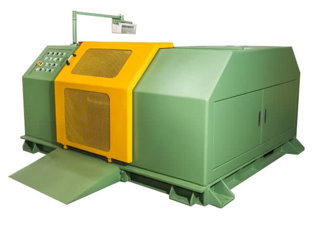
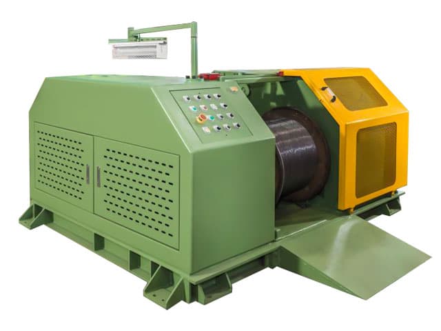
Design features of the horizontal spooler RGT-2000
- Take-up range from Ø1.6 to Ø5 mm.
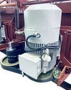
- This Horizontal Spooler uses a 75HP AC inverter SIEMENS motor (3-phase) with a MITSUBISHI inverter drive.
- Take-up speed is synchronized to outlet capstan block.
- The Spool / Bobbin:
- Spool size: DIN-800 (to be advised by Buyer).
- The horizontal spooler equipped with elevation mechanism for easy loading and unloading of spool (bobbin).
- The chasis runs by cylinder for positioning of the spooler plate - left / right, up / down.
- Maximum take-up weight 1000 kg (excluding spool weight).
- Control mechanism via pneumatics.
- The Traverse Mechanism:
- Reducing motor (0.5 HP) for wire traversing.
- Speed control by inverter drive.
- Adjustable constant speed from empty to full spool.
- The traverse width and lay are fully adjustable.
- 2 sets of straightening rollers are made of SKD-11 high-carbon tool steel, hardened. At the request of the Customer, additional sets of rollers for different wire diameters will be supplied.
- The RGT-2000 horizontal spooler available for linking and synchronization with other machine line.
- Disc brake system manufactured by Suntes (Japan) or similar quality. Winding machine stop time:
- Normal Stop: 30 ~ 50 sec without wire breaking.
- Quick Stop: 10 sec without wire breaking.
- Emergency Stop: 0.5 ~ 3 sec with wire breakage.
- Acceleration time: 30 seconds from zero to max speed.
- Equipment Power Source: 380V / 50Hz / 3 Phase.
- Safety Guard and Frame: the equipment has a protective steel guard with a sliding door for quick and easy access to spool / bobbin.
Features of horizontal type wire drawing line
Electrical equipment components
- 3 phase AC Motor from SIEMENS, top quality assurance MITSUBISHI Inverters from Japan with high initial breakaway torque smooth running at low speeds (1Hz@200% torque).
- PLC Electrical Cabinet with dust filtration and constant voltage regulator to prevent electrical damage during power irregularities.
- Electrical components are of high-quality products with national license.
- The power supply shall be of 3-phase 4-wire system with low-voltage control circuit consisting of 24V.
- When the voltage of the power grid fluctuates within ±5%, the equipment is required to ensure normal operations under such condition.
- Safety Measures : overload protection, line snarl protection, overheat protection.
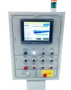
- Main Control Console (operator station): Touch Monitor & physical push-Buttons ∧ switch.
- High-precision sensors from France.
- Mitsubishi or SIEMENS PLC Control System.
Mechanical components of equipment
- All Buttons With Dust Protection.
- Helical (Bevel) Gearboxes and first set of Hypoid Gear are made in Taiwan for top quality assurance. Material: forged SNCM & SCM alloy steel, after hardness treatment, reaching HRC59°±2°. The Gears have been processed with high precision German machinery with secondary grinding of JIS standard for tooth surface treatment to produce a quality life of up to 10 years. This type of gears are suitable for long operations under high work loads.
- An oil level controller is installed in the gearbox to prevent the gears and bearings from damage due to insufficient oil level, oil loss, oil clog, and high temperature; the machine will automatically stop and notify the operator through the HMI monitor to prevent further damage to the gearbox.
- Gearbox cooling system with magnetic filtering to prevent metallic residual generated from long term gear friction, thus contaminating the gearbox oil. This system was implemented to protect the gears, bearings, and oil seals and achieve a longer service life while lowering the cost of maintenance.
- Bearings of SKF or similar precision quality. Oil seals are from renowned Japan NOK brand or similar quality.
- Exceptional quality disk brakes from Taiwan with electrical type braking system from Lenze (Germany) or similar quality.
- Material of the Gears are made of SNCM alloy steel with material of transmission mandrel direct from Japan.
HMI Main Control Console
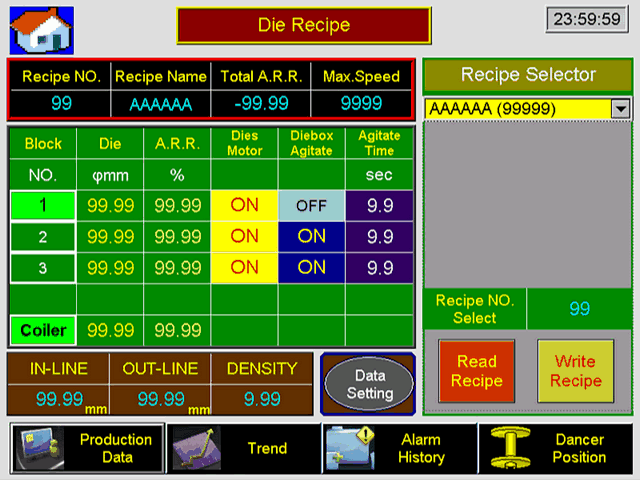
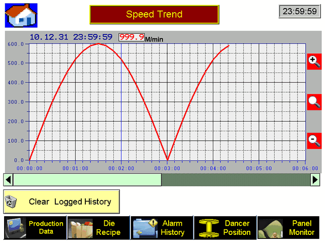
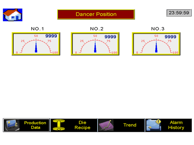
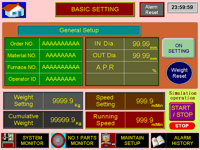
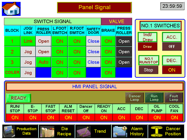
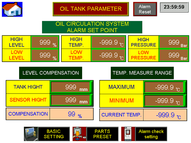
HMI control console includes a touch display monitor with keyboard interface for setting input and output parameters of each individual block. The HMI console will display all various statuses and parameters, not limited to but including Line Speed, Frequency & Current, the Reduction per Draft, Individual Capstan Speed, and all possible warnings & errors. Memory of errors and alarms are recorded on the system's history log for analysis and troubleshooting.
Industry 4.0 Hardware & Software
Optional Industry 4.0 hardware and software for horizontal type wire drawing line:
- HMI console provides all possible monitoring; including but not limited to Line Speed, Reduction Rate, Power Consumption, Power Ratio, Output Capacity, Dancer Position, Signals & Alarm, Alarm History Log and more (refer to interface pictures below for more details).
- HMI will display all possible errors and notification and if deemed necessary will automatically stop the machine line to prevent further damage to the drawing machine.
- Allows input for 30 programmable sets of wire drawing data recipe.
- Graphic data to provide quick analysis of output production relative to the time and day.
- Optional PLC ethernet networking transmodule to enable LAN connection for remote diagnosis and troubleshooting. Together with an industrial computer and data server (customer is responsible for said equipment implementation), a data management system can be implemented to allow for level 0 to level 2 monitoring.
Auxiliary equipment
At the request of the Customer, the horizontal wire drawing line can be equipped with a Roller Type Wire Sharpening Machines and welding machines for electric butt welding of wire ends (3 - 30 KVA).